Gear Box (Fall 2019)
For my final project for Design of Machine Elements we were tasked with designing a gear box. Each group in the class was given a different specification to design. For my group the specifications were that it needed to have a gear ratio of 3.5 with a 1% variation, 7 HP with a 1.5 overload factor and the input would spin at 1800 RPM. To design the gear box, we started with finding a set of gears that were the correct gear ratio and were strong enough to withstand the loads. To do this we made an Excel worksheet that took the specs of the gears and calculated the loads on the gears. We then compared this back to the spec sheet to see if they were strong enough. Once we found gears that were strong enough, we used the bore diameter to determine the appropriate design that could handle the load on the shaft and the key. Using the preliminary shaft diameters and the forces on the key, the length of the key could then be calculated.
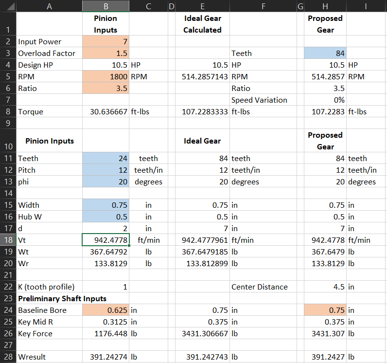
Excel worksheet for calculating gear force

Excel worksheet for calculating gear force
We then calculated if the shaft was strong enough to take the loads of the gears. We confirmed the calculations using a FEA analysis. When both the FEA and the Excel calculations matched up, we knew that the math was correct and that the shaft was strong enough.
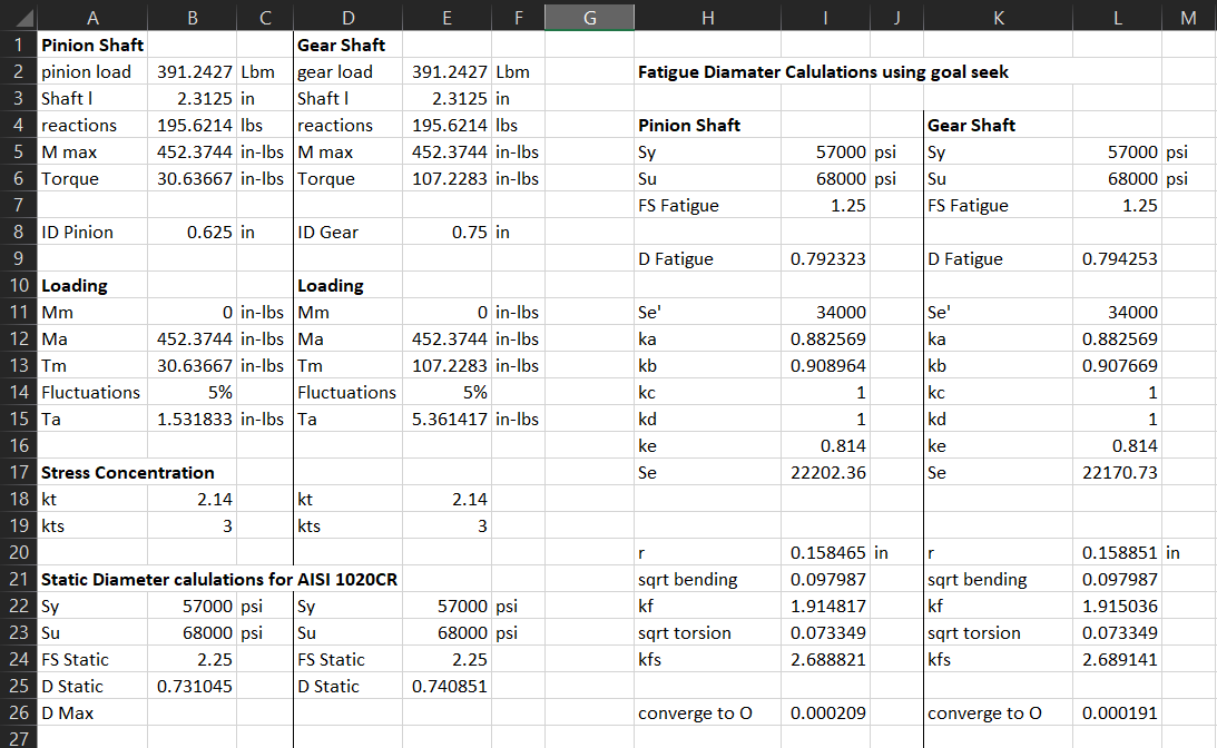
Excel worksheet for calculating shaft forces
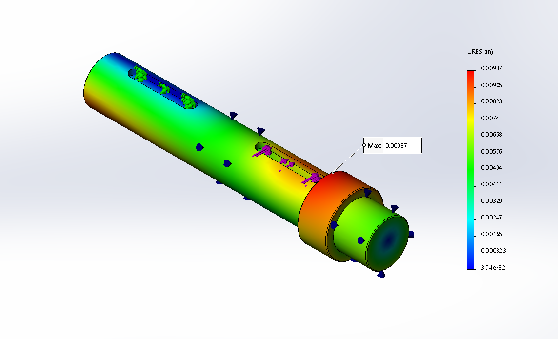
FEA analysis of shaft
The Excel worksheet below calculated how strong the bearing needed to be to support the loads. The last design requirement was 4,000 hours of use. Using this data we then looked for bearings that would meet the load requirements.
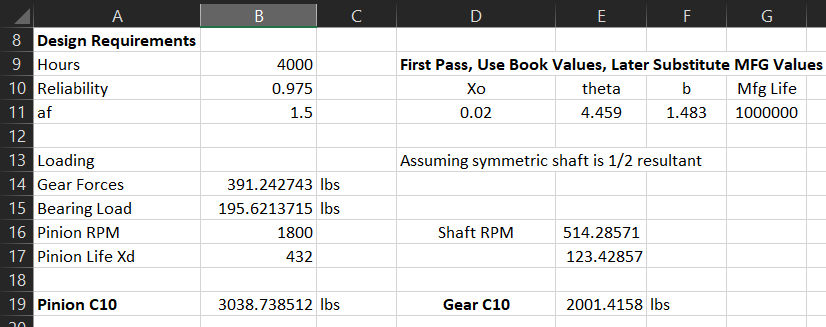
Excel worksheet for calculating shaft forces
After all the calculations were completed all of the parts were made in Solidworks as well as the bearing holders, the case and all the hardware to connect everything together.
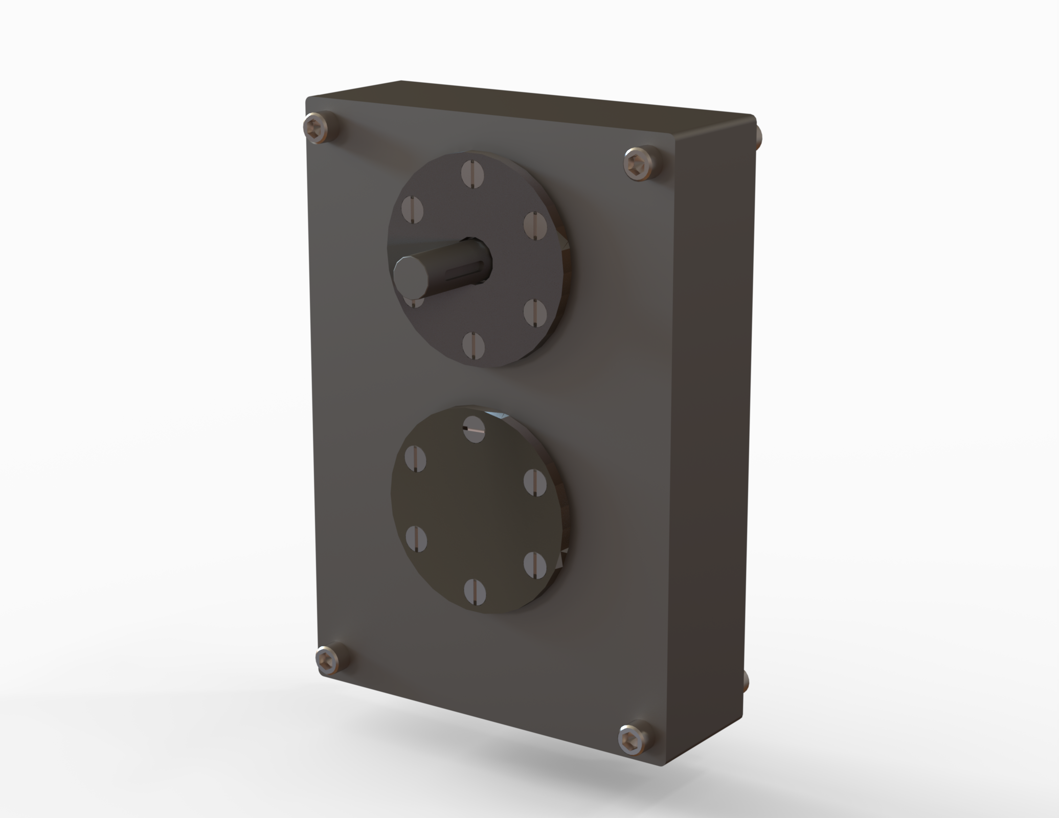
Render of the final design
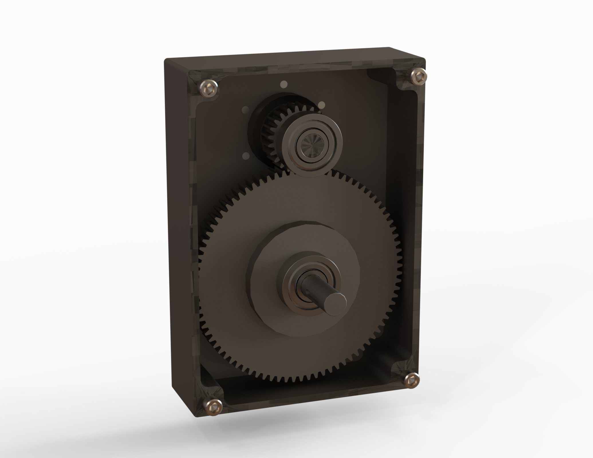
Gearbox with the front removed