RC Buggy (Fall 2019)
For my final project for Computer Aided Manufacturing my group and I were tasked with designing and making a buggy. The requirements for the project were to design and cut most of the parts and the rest would be 3D printed. We had a budget for the 3D printing lab on campus. We decided to model the buggy off an old tank that we thought looked cool, and would fit the proportions of what was needed. We drew up a few ideas based off of some reference pictures with estimates of basic dimensions. We then started to model parts of the buggy. I modeled the side plates and the adapters that held the wheels to the motors. I also modeled the motors and controller board so that we could determine how they would be mounted. As parts were being designed, I put them together to make sure all of the parts would fit together correctly.
I made the CAM for the wheels and the side plates with input from the rest of my group. The CAM for the sides was fairly simple as they were designed for most of the material to be removed by a 1/2" endmill. There were also a few drilled holes that needed to be cut to finish the part. After cutting this part twice for both sides of the buggy we face milled a sacrificial plate. This was used to bolt on the parts to start to cut material off the back of the part.
The next parts that were cut were the wheels. The outside of the parts had been simple to cut but the more intricately designed inside section required a lot of cutting with a 1/4" endmill. The inside of the wheel CAM needed a good bit of adjusting so that it would not cut anything it shouldn't in other operations. The original plan was to use soft jaws to cut off the stock on the back and do more cutting on the back of the part. We lost class time because of snow so we had to change our plan. The new plan for removing the rear stock was to chuck them into the lathe. To do this we rough cut the corners off with a bandsaw to make the part more round so we would get less of an interrupted cut. We then put them in the chuck using short parallels to get the part in with little runout. By measuring the width of the back we knew how much to cut off of the part.
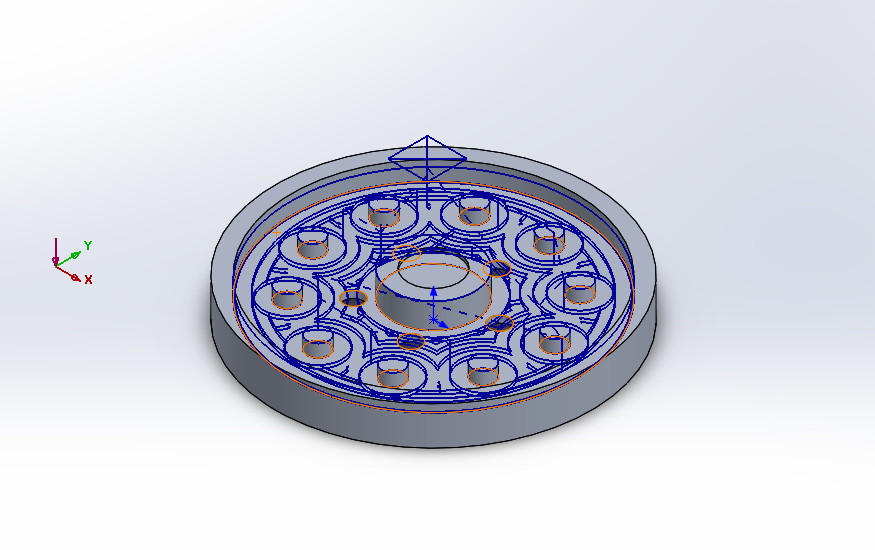
Tool path for inside of wheel
Render of final design
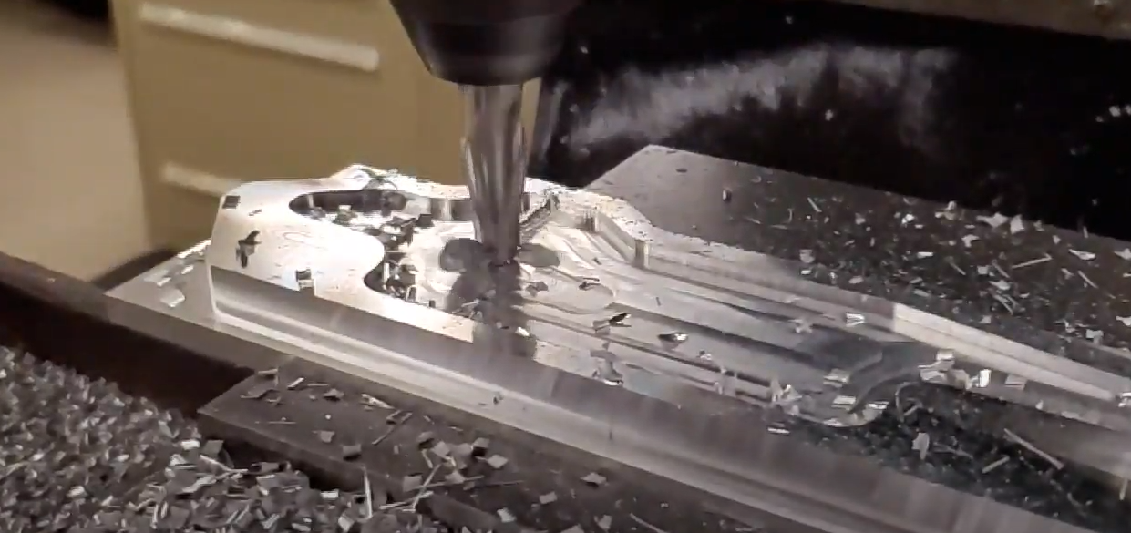
Machining of side plates
We decided to 3D print the body of the buggy out of ABS because it was cheap to print and did not need to be that acurate. The adapters for attaching the wheels to the motors were printed on a Form 2 because we wanted these parts to be more accurate. That way they would fit well on the motor shaft. We also printed a beam that connected the bottom of the two sides to make the buggy more rigid.
In the end the buggy could have performed better. The tolerances of the wheel mounting were too loose so the wheels would not spin that freely. This caused issues when turning. But while it could have performed better, it met the design requirements of the project.

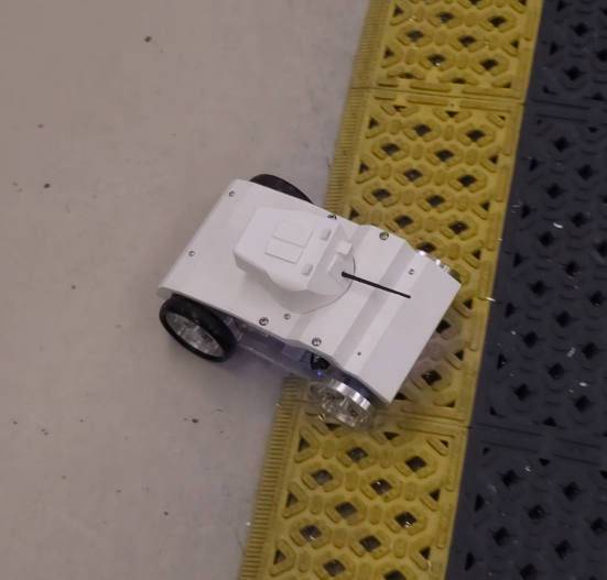
Final Build